All righty. I got the power supply working perfectly, and I even got the DPDT switch working correctly. Now, however, I am backtracking a bit. Yes, this system is able to control the directions of the actuators, but it has no way of controlling the speed. In our application we have no use for a machine that pulls apart at 0.4 in/s. Nope. Therefore, I need to get my hands on another MultiMoto shield and get it working with an Arduino. That's all that's needed, man.
For the bulge test stuff, I talked with the machine shop and got a general feel for what they can and cannot do. My drawings have been in metric units, but they work entirely in imperial units. Darnnnn. After looking up pricing of parts, I understand why America is staying with imperial units instead of switching over with the rest of the world. Things are just cheaper! Therefore, I will modify my dimensions and part decisions to go with the cheaper options.
I feel confident that all of this will end up fine. Steady work, no rush.
Wednesday, March 1, 2017
Thursday, February 23, 2017
Bulge test dimensioning
The bulge test parts must be made. The idea for this is that a nitrogen tank will supply nitrogen at incremental pressures to a thin foil until it bulges and breaks. In order for this to work, a fixture is needed to hold the foil in place and apply pressure.
One aspect of this test includes o-rings. Page 109 of this reference gives me some baseline to go off of for my o-ring groove dimensions. I'll be using a 2 mm thick o-ring, just because it looks like a good size.
Wednesday, February 22, 2017
Feel the power
My power supply came in the mail, yay! I ended up buying this one. If it performs as advertised, it should give us 12V up to 30A. Cool! It should work well. I still need to figure out how to wire up everything though. I have a wall plug that I cut open, but I haven't figured out which wire should go into which port.
This website might help determine what each wire should be attached to (wall to power supply). (EDIT: The European wiring worked! Green/yellow ground, blue neutral, brown line)
How to wire a DPDT instructables looks good enough in teaching me how to wire up the DPDT switch I bought last week. By the looks of it, I may need to do a little bit more shopping for some electrical connections and possibly a crimping tool. All I need is to get this thing moving. After it moves, we may run into more issues. (Yay)
If you are reading this, you may have by now figured out that I am just using this as a place to drop a bunch of links for my own future reference. My plan is working out perfectly! hahahahahaha
Thursday, February 16, 2017
Switching things up
Frustration was the word of the day yesterday. I guess frustration stemming from inexperience. The motor shield appeared to be in place to be usable, and it actually worked for a little bit of the time, but that was until it all kind of went wrong.
Some of my soldering came loose on the big motor/power attachment pins, which prompted a re-solder. I'm not the one who performed the re-solder, and I have a feeling like that might have messed things up a bit. I tried hooking up the power to the shield again, and the current was quite high. The voltage was low because of the high current draw. Yeah, things did not end well... I knew that because of the large spark that was momentarily about the size of a quarter. Gah. Frustrating.
While I am able to get the Pololu shield working, it requires very careful soldering. Long story short, I am not willing to put that level of care into it at this point in time. We are going to buy a power supply and connect the motors with some switches.
Three switches will be used: one to switch on/off the x-axis, one to switch on/off the y-axis, and one as a master switch. The master switch is a DPDT center-off switch. This allows for both reverse and forward direction. The only concern is that we won't really be able to control the speed of the actuators. Maybe a rheostat could be used for that?
So yeah, that's where we are with that situation. I have wire and three switches from RadioShack. The store ended up being in a "going-out-of-business" state, so I got all three switches for around $6. Sweet!
Each switch is rated for 12 Volts and 25 Amps (or something like that). Now I just need a power supply that can give us exactly what we need. 12 Volts. From what I understand, a power supply amperage rating does not indicate that it will actually give max power all the time. If it is rated for 20A, it has the ability to supply 20A of current, but will only supply whatever amount the load requires.
Tuesday, February 14, 2017
Soldering the Pololu shield
Today has absolutely flown by. After figuring out how to transport my roommates soldering stuff to the engineering building, I had to get my confidence sufficiently up to complete the job. So what did I do? I just kind of jumped into it.
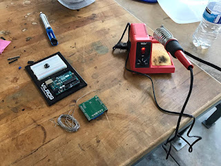


Figure 1: Soldering setup
I had a nice little setup in the lab, as can be seen in Figure 1. A slightly wet sponge, a heating up soldering iron, and shaky hands.

Figure 2: not the prettiest job
I'll be the first to admit that my solder job doesn't look the best. I tried this alignment technique using the Arduino pins themselves, but I think the pins are misaligned by a little bit, so my solder job went a bit misaligned. That is just for two rows of pins though, as seen in Figure 2. Two other rows came out totally fine. Even the jumper pins and motor/power junctions came out decently well.

Figure 3: Oh babyyyy
Figure 3 shows the underside of this motor shield. It's the result of my first time soldering. Happy days! Next up I'll have to find out if it actually works as it's supposed to work. I really hope it does. Maybe I'll hook up a low power DC motor I have first to make sure it actually works, and then I'll hook up the big-boy actuators.
I hope I didn't burn anything..
Here are a few more pics of the shield attached to the Arduino.


Monday, February 13, 2017
Psyching myself up to solder
Oh boy, the Pololu motor shield came in! It came in yesterday, actually, and it's smaller than I thought it would be. I'm going to have to learn how to solder now. I mean, I could probably do it ok, but I need to make sure that I don't mess anything up. I want it to be operational as soon as possible.
So with that being said, I've been watching some videos that involve soldering or teach how to solder.
So with that being said, I've been watching some videos that involve soldering or teach how to solder.
Video 1 - A shield being soldered for Arduino
Video 1 shows the first video that I've watched. It's just a guy soldering stuff. I'm anticipating mine to work a bit differently, though, because I have pins that have inserts for 22 AWG wire at the top. Hmm.
Video 2 - Soldering for beginners
Video 2 gave me some good hints on how to solder. Since I'll be soldering small components on a board, I will have to keep the temperature on the low side (600 degrees Fahrenheit or 315 degrees Celsius).
Steps I've noticed:
- Clean off connections and soldering iron.
- A wet sponge can help for cleaning off the iron.
- Apply some solder to the tip of the iron first.
- Heat up the metal that you want to solder.
- Apply solder to the heated metal (and not the iron tip).
- This is because there is flux in the solder which helps make the connection.
- Quickly pull up the iron to get that nice bubble look
- Don't heat the board for too long.
I think I can do this! I'm just somewhat worried about the size of the soldering iron tip. My roommate has an iron, but the tip is quite large. I have an iron too, but it has no way to control temperature. I can find out if the engineering building here has an iron for me to use.
Video 3 - More soldering!
Ok, by the ending of Video 3, I feel pretty good about the steps. I should practice on some cheaper items first, though. Cool cool. I will tackle this issue tomorrow when I have free time.
Thursday, February 9, 2017
Specs: Arduino motor shields
It's all fine and dandy that we have some linear actuators in our possession, but moving them is another issue. We need to control the speed at which they move outward, along with some sort of initialization logic. The actuators need to all start with the grip ends at the needed locations, followed by being retracted, causing the tension that we are looking for.


In order to control the movement, we are using an Arduino Uno with a motor shield. The particular motor shield that we are hoping to use is the Robot Power MultiMoto. It appears to be perfect for our needs.

Figure 1 - Robot Power MultiMoto
Some specs of the MultiMoto (seen in Figure 1):
- 6.0V-36V battery voltage
- Four independently controlled channels
- 6.5A continuous current on each channel (8A max)
- Nearly blow proof
Wow, great! Our actuators have a limit of 6.5A as well. We need to give 12V to each actuator, so that's covered here too.
But sometimes things are too good to be true.. We tried it out and something went wrong. I wasn't actually there for this, but the four actuators were all moving ok, one of the wires came out (or something like that), and it was powered down. Somehow the Arduino was fried. The MultiMoto doesn't seem to be functioning either. So we are in process of replacing the MultiMoto.
In the meantime, I am trying to find something a bit cheaper to buy so I can at least power two of the actuators. If I can get the machine working in one axis, it would be easy enough to replicate in a second axis.
The requirements for my personal motor shield purchase are:
- Able to handle 12V
- Power two motors
- Able to handle at least 3A per channel

Figure 2 - Arduino Motor Shield R3
I found these handy dandy instructions to help set up an Arduino Motor Shield R3 (as seen in Figure 2) (http://www.instructables.com/id/Arduino-Motor-Shield-Tutorial/?ALLSTEPS).
It appears that this shield is really only able to handle 2A per channel (for two motors), or 4A for a single channel. Hmmm. Will that be enough? I guess if anything, I can control on actuator. It will set me back about $25 (amazon link).
Figure 3 - Pololu Motor Driver shield
But I shouldn't settle for less than what I need. Figure 3 shows another shield I found. It's the Pololu MC33926 dual motor driver shield for Arduino. Again, it'll set me back $36. But it seems to have the specs that I'm looking for as a short term replacement. 5V-28V operating voltage. 3A continuous output current per motor (5A peak). It would just require a little bit of soldering, which I'm sure I could do. Pololu motor shield manual
I feel like I should spend an extra $11 to be able to power two actuators sufficiently instead of just one. If this ends up working well and the replacement MultiMoto still proves problematic, we could incorporate two of the Pololu's.
You may have noticed I've posted links to Amazon Prime sources. This is because I have Prime for a month and I'm trying to take advantage of it! If I can get these parts in a day, it would really help me have some more time for finishing it up too. I don't really want to deal with long shipping times. I have work to do.
Subscribe to:
Posts (Atom)